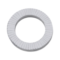
RP 55 cavity fire barrier sock
Joint cord RP 55
FUGENSCHNUR 12MMX100M

Register now and access more than 125,000 products
- Area of application: for use in the J 2 joint system
- Tested for joints between components with the same load and deformation, as well as shear loads, which may take the form of step joints (multi-step joints) and linear perpend joints (single-step joints)
- Tested joint widths
10 to 55 mm - Quick and easy to apply the flexible and elastic joint cord
- Fixing the joint cords as an assembly aid with non-flammable adhesive is permitted and does not negatively affect the fire resistance class
General type approval Z-19.23-2098
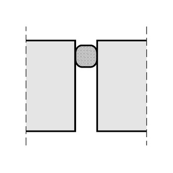
Installation examples up to F 90 joints between components with similar load
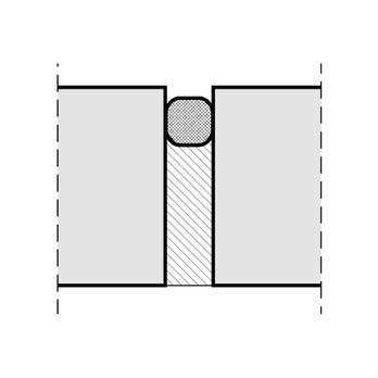
Installation examples up to F 90 joints between components with the same load (Combustible) filling
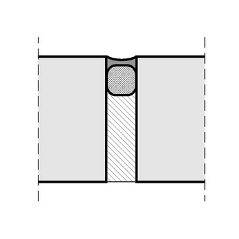
Installation examples up to F 90 joints between components with the same load with sealing and (combustible) filling
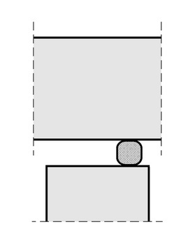
Installation examples up to F 90 joints between components with similar load
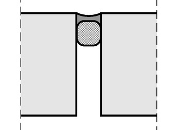
Installation examples up to F 90 joints between components with the same load with sealing
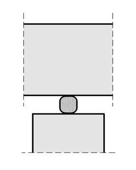
Installation examples up to F 90 joints between components with similar load
General type approval Z-19.23-2098
Further information and technical details are provided in the current proof of applicability.
The application images shown are for example purposes only. The exact installation situations/applications can be found in the proof of applicability.
Datasheets(X)
Mineral fibre sealant cord (RP 55 short joint cord) for sealing joints in ceilings of fire resistance classes F 30-F 120 and load-bearing and non-load-bearing space-enclosing solid walls of fire resistance classes F 30-F 120 in accordance with the general type approval Z-19.23-2098.
Number of rolls | 5 PCS |
Length of roll | 20 m |
Diameter | 12 mm |
Min./max. joint width | 5-10 mm |
Fire resistance rating | F120 |
Building material class | A1 - Non-flammable |
Colour | Grey brown |
| Joint width | Cord diameter | Fire resistance class of wall or ceiling components Minimum component thickness (d) | |||||||
| Number of joint cords for joints between components with similar load | Number of joint cords for joints between components with shear stress | ||||||||
| Nominal diameter and number of layers of the joint cord to be installed The dimensioning – nominal diameter – and the number of layers of the joint cord RP 55 to be installed, depending on the required fire resistance class and the permissible joint widths, also taking into account the expected movements, are shown in the table below. | |||||||||
| F 30 A d> 100 mm | F 60 A d> 100 mm | F 90 A d> 100 mm | F 120 A d> 120 mm | F 30 A d> 120 mm | F 60 A d> 120 mm | F 90 A d> 150 mm | F 120 A d> 150 mm | ||
| < 10 mm | 12 | 1 | 1 | 1 | 2 | 1*) | 1*) | 2*) | 3 |
| < 12 mm | 15 | 1 | 1 | 1 | 2 | 1*) | 1*) | 2*) | 3 |
| < 17 mm | 20 | 1 | 1 | 1 | 2 | 1*) | 1*) | 2*) | 3 |
| < 27 mm | 30 | 1 | 1 | 1 | 2 | 1*) | 1*) | 2*) | 2*) |
| < 37 mm | 40 | 1 | 1 | 1 | 2 | 1*) | 1*) | 2*) | 2*) |
| < 47 mm | 50 | 1 | 1 | 1 | 2 | 1*) | 1*) | 2*) | 2*) |
| < 55 mm | 60 | 1 | 1 | 1 | 2 | 1*) | 1*) | 2*) | 2*) |
| *) In the case of shear stress, the (lower) joint cord must be installed in ceilings offset back by > 25 mm; in walls, in the case of more than one joint cord, the two outer joint layers must be arranged offset back by > 25 mm. | |||||||||


