


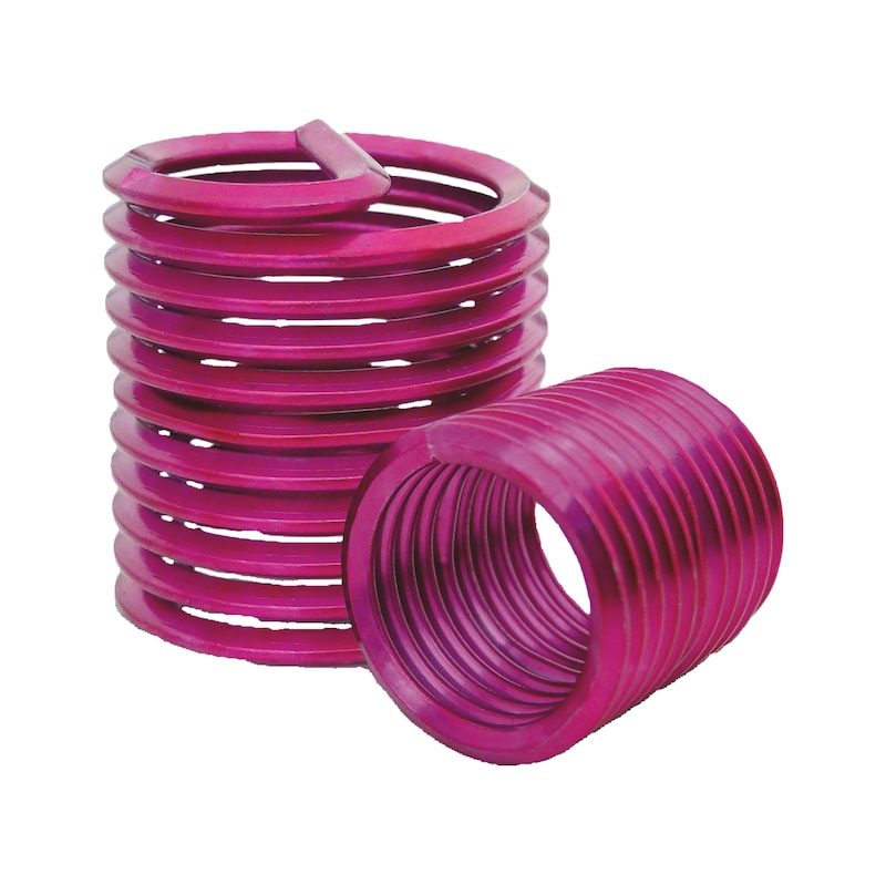


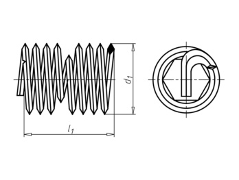
Helical insert W.TEC® INSERT COIL Screw Grip
Helical insert SG A2 W.TEC series
HELCINRT-SG-A2-M8X8
W.TEC


Register now and access more than 125,000 products
Perfect combination of space-spacing and wear-resistant thread strength
- In low-strength metal materials
- In plastics
Optimal force distribution
Flexibility of the thread inserts compensates for pitch and angle errors
Thread insert sits securely
Minimised thread friction torque and minimised torsional stress
Increased corrosion resistance
Space and weight minimisation
Smaller number of required connection points and/or reduced screwing dimensions
Costs minimised
By reinforcing the thread, which effectively minimises the repair costs
Integrated loss protection
The clamping torques are comparable with the values of DIN 267 Part 15 or DIN EN ISO 2320.
The clamping torques are comparable with the values of DIN 267 Part 15 or DIN EN ISO 2320.
Datasheets(X)
CAD data (available after login)

A resistant thread in 4 steps:
Step 1:
Drill a core hole or drill out the damaged thread
Step 2:
Create a receiving thread
- By cutting using screw tap
OR
- Without cutting using thread moulding for an even more resilient receiving thread
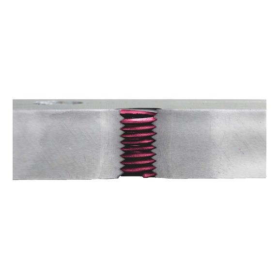
Step 3:
Set the thread insert
- The helical insert can be mounted both mechanically and also by hand using the corresponding screw-in tool.
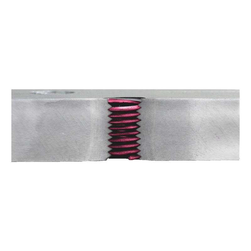
Step 4:
Break the pin
- Separate the follower pin by tapping gently on the predetermined break point with a pin breaker, and then remove. Automatic pin breakers are also available for series production.
 | |
Material | Stainless steel A2 |
Surface | Plain |
Design | With loss-preventing retainer |
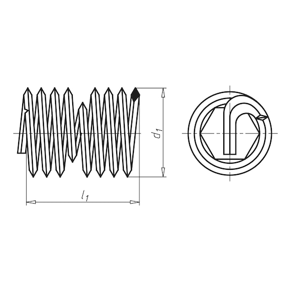
Thread type x nominal diameter | M8 |
Length built-in state (l1) | 8 mm |
Outer diameter (d1) | 9.7 mm |
Thread form | Standard metric thread |
Pitch | 1.25 mm |
Core hole diameter | 8.3 mm |
Min. core hole depth | 13.63 mm |
Required thread depth at stud hole | 12.38 mm |
Locking device operating principle | Clamping by thread geometry |
Locking function | Locking against loosening by clamping |
| Determining the nominal length (reference values) | ||||
| Material strength of workpiece Rm in N/mm² | Nominal lengths for thread inserts depending on the strength class of the screw or the yield strength of the screw material in N/mm² | |||
| 5.8/400 | 8.8/640 | 10.9/900 | 12.9/1080 | |
| up to 150 | 2 d | 2.5 d | 2.5 d | 2.5 d |
| Over 150 up to 200 | 1.5 d | 2 d | 2 d | 2.5 d |
| Over 200 up to 250 | 1.5 d | 1.5 d | 2 d | 2.5 d |
| Over 250 up to 300 | 1 d | 1.5 d | 1.5 d | 2 d |
| Over 300 up to 400 | 1 d | 1 d | 1.5 d | 1.5 d |
| Over 400 | 1 d | 1 d | 1.5 d | 1.5 d |
| Thread inserts with a nominal length that corresponds to the material strength of the workpiece and the strength class of the screw (in accordance with the table) achieve the minimum breaking force of the screw as per ISO 898-1 | ||||
| Clamping torques for W.Tec® insert coil type: "screw grip" | ||
| Thread dimension | Max. clamping torque [Nm] | Min. clamping torque after the screw has been turned 5 times [Nm] |
| M2 | 0,12 | 0,003 |
| M2.5 | 0,22 | 0,06 |
| M3 | 0,44 | 0,1 |
| M4 | 0,9 | 0,16 |
| M5 | 1,6 | 0,2 |
| M6 | 3 | 0,3 |
| M8 | 6 | 0,6 |
| M10 | 10,5 | 1 |
| M12 | 15,5 | 1,6 |
| M14 | 24 | 2,3 |
| M16 | 32 | 3 |
| M18 | 42 | 4,2 |
| M20 | 54 | 5,3 |
| M24 | 80 | 8 |
| M30 | 108 | 12 |
| M36 | 136 | 16 |
Last viewed
Hexagon Socket Head Cap Screw ISO 4762/DIN 912, A2-70 stainless steel
pias® drilling screw with hexagon head and drill tip Case-hardened steel, zinc-plated, blue passivated
Open-end plug tool wrench
3/8 inch socket wrench insert metric, hexagon, short
Hexagonal bolt with thread up to head
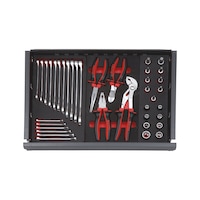
Tool assortment 38 pieces
HSCo stepped spot weld drill bit
Hexagonal nut, flat profile
HSCo green-ring machine tap for blind holes DIN 371/376
Metric combination wrench with POWERDRIV®